Forum Replies Created
-
AuthorPosts
-
Aman
ParticipantHere You get the full project of Digital thermometer using LM35 Temperature sensor and Arduino.
https://www.circuitspedia.com/arduino-lm35-temperature-sensor-arduino-code-with-lcd-display/
Aman
ParticipantWhat do you want to say about that ?? Please clarify your question
Aman
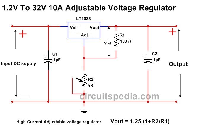
Participant10A High Current Adjustable Voltage Regulator using LT1038
The LT1038 is a three terminal adjustable voltage regulator which is capable of providing of 10A output high current at 1.2V to 32V range. According to datasheet LT1038 has following properties
In addition to excellent load and line regulations, the LT1038 is fully protected by current limiting, safe area protection and thermal shutdown. New current limiting circuitry allows transient load currents up to 24A to be
supplied for 500ms without causing the regulator to current limit and drop out of regulation during the transient.
On-chip trimming of initial reference voltage to ±0.8% combined with 0.4% load regulation minimize errors in all
high current applications. Further, the LT1038 is manufactured with standard bipolar processing and has Linear Technology’s high reliability.
For more go to http://www.circuitspedia.com/10a-high-current-adjustable-voltage-regulator-circuit-diagram-using-lt1038/

Aman
ParticipantAt which side of Relay you see the 3 pins or 3 terminal– This side the middle pin of both side pin is the Common (COM) for the Load input (AC or DC). And both side pins are the DC Input supply pin for the coil of relay.
So the which you see the 3 terminal – here you both side (Except middle) pins are connect with DC supply for relay input.
And which side you see the only 2 terminals – These 2 terminals are for Load Output . In which one is NC (normarrly Connected) and one is NO (Normally opened) . For finding which pin is NO and Which Is NC use the multimeter or ant continuty tester.
OR
Generally On PCB Relays -there are pin connection name is denoted on relay body near the all pins.
For more go to http://www.circuitspedia.com/
Aman
ParticipantPlease check this link.
http://www.circuitspedia.com/dc-fan-speed-regulator-circuit/
DC Motor speed controller using PWM. very smoothly and noise free. tested on 12v 1 A DC Fan.
Aman
ParticipantHere is a link of circuit diagram and With Live demo video of DC motor speed controller . This works on pwm, can easyly used for 1A motor. Very Smoothly . Tested on 12v 1A DC Fan
Link is http://www.circuitspedia.com/dc-fan-speed-regulator-circuit/
-
AuthorPosts
