EngineersGarage

  • Engineers Garage Main Site
  • Visit our active EE Forums
    • EDABoard.com
    • Electro-Tech-Online
  • Projects & Tutorials
    • Circuits
    • Electronic Projects
    • Tutorials
    • Components
  • Digi-Key Store
    • Cables, Wires
    • Connectors, Interconnect
    • Discrete
    • Electromechanical
    • Embedded Computers
    • Enclosures, Hardware, Office
    • Integrated Circuits (ICs)
    • Isolators
    • LED/Optoelectronics
    • Passive
    • Power, Circuit Protection
    • Programmers
    • RF, Wireless
    • Semiconductors
    • Sensors, Transducers
    • Test Products
    • Tools
  • Advertise
You are here: Home / Topics / How to interface GPS with PIC18F4550 Microcontroller

How to interface GPS with PIC18F4550 Microcontroller

|

Projects › Projects › How to interface GPS with PIC18F4550 Microcontroller

  • This topic has 5 replies, 3 voices, and was last updated 14 years, 1 month ago by AJISH ALFRED.
Viewing 6 posts - 1 through 6 (of 6 total)
  • Author
    Posts
  • March 30, 2012 at 3:53 am #1539
    jack
    Participant

    hello…i’m doing the same thing…but the LCD keep no showing any~ what the problem??? izit programming or circuit problem?? thanks for help…


    http://www.engineersgarage.com/embedded/pic-microcontroller-projects/gps-interface-circuit


    March 30, 2012 at 9:10 am #7356
    nikhiljain
    Participant

    It should be problem with the circuit that you have made. Try to find the problems with your project.

    April 2, 2012 at 3:01 am #7379
    jack
    Participant

    how to test any communication in between the rs 232….

    April 21, 2012 at 2:22 am #7526
    jack
    Participant

    facing problem..

    lcd show null character

    Image0325.jpg


    Image0325.jpg


    Image0326.jpg

    April 21, 2012 at 2:24 am #7527
    jack
    Participant

    wysiwyg_imageupload:4450:

    April 27, 2012 at 6:27 pm #7561
    AJISH ALFRED
    Participant

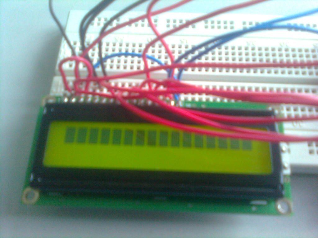
    I can see from the picture that your lcd not even get initialized. Check all the pin connections of lcd. Check the voltage on R/W pin, it should be zero. Also adjust (reduce) the contrast by adjusting the variable resistor connected to pin3. Try increasing the delay slightly wherever it is used.

  • Author
    Posts
Viewing 6 posts - 1 through 6 (of 6 total)
  • You must be logged in to reply to this topic.
Log In

RSS Recent Posts

  • washing machine motor wiring June 15, 2026
  • Mitsubishi Electric IPM module lot code format - how to decode? June 14, 2026
  • Replacement IGBT for DGG4015 for Honda Motorcycle ECU June 14, 2026
  • TDK Lambda ESS 500-20-11-D-LB-RSTL Parallel Operation June 13, 2026
  • Programmable 1kV DC Power Supply – Budget ~$600 with Display June 13, 2026

Stay Up To Date

Newsletter Signup
EngineersGarage

Copyright © 2026 WTWH Media LLC. All Rights Reserved. The material on this site may not be reproduced, distributed, transmitted, cached or otherwise used, except with the prior written permission of WTWH Media
Privacy Policy | Advertising | About Us

Search Engineers Garage

  • Engineers Garage Main Site
  • Visit our active EE Forums
    • EDABoard.com
    • Electro-Tech-Online
  • Projects & Tutorials
    • Circuits
    • Electronic Projects
    • Tutorials
    • Components
  • Digi-Key Store
    • Cables, Wires
    • Connectors, Interconnect
    • Discrete
    • Electromechanical
    • Embedded Computers
    • Enclosures, Hardware, Office
    • Integrated Circuits (ICs)
    • Isolators
    • LED/Optoelectronics
    • Passive
    • Power, Circuit Protection
    • Programmers
    • RF, Wireless
    • Semiconductors
    • Sensors, Transducers
    • Test Products
    • Tools
  • Advertise